Long time no see, eh? I’ve created a short guide on the most basic binary adders and their purpose, as well as some different types of adders.
A binary adder is a logic circuit that takes multiple inputs (binary) and “adds” them together.
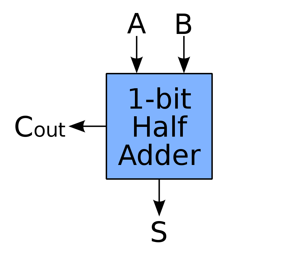
Binary adders are represented in an odd way, that is easy to understand when you get the hang of it. It has two outputs (C and S), C being carry and S being sum. C is a value that is carried (an overflow) to the next row.
If you read my previous guide, you know how truth tables work. Adders can also be represented in truth tables. A table for a half adder (two inputs) is represented below.
Think of C and S being in the same column, where both A and B are 1, C is 1 and S is 0, or 10.
| A | B | C (output) | S (sum) |
|---|---|---|---|
| 0 | 0 | 0 | 0 |
| 0 | 1 | 0 | 1 |
| 1 | 0 | 0 | 1 |
| 1 | 1 | 1 | 0 |
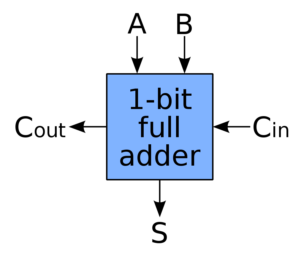
That is the circuit for a half adder. A proper full adder takes 3 inputs, with the same C and S outputs. To calculate the sum, use 2C^output + S.
| A | B | C (input) | C (output) | S (sum) |
|---|---|---|---|---|
| 0 | 0 | 0 | 0 | 0 |
| 0 | 0 | 1 | 0 | 1 |
| 0 | 1 | 0 | 0 | 1 |
| 0 | 1 | 1 | 1 | 0 |
| 1 | 0 | 0 | 0 | 1 |
| 1 | 0 | 1 | 1 | 0 |
| 1 | 1 | 0 | 1 | 0 |
| 1 | 1 | 1 | 1 | 1 |
For a more graphical representation, open this detail box.
Half-adder
Half-adder symbol
Full-adder
Full-adder symbol
I hope you enjoyed this lesson, it was interesting to make! I am not sure when I can continue these guides, but I’ll try to get at least one out this month.