Minecraft Username: iuriineves
Have you read the Read Before Posting post?: Yes.
Your favorite thing about redstone: The way it can mimic real life circuitry.
A build you have made which demonstrates redstone knowledge (This is your trial build): A 4bit ALU capable of bitwise (OR, NOR, XOR, XNOR, AND, NAND) and arithmetic (SUM, SUB) operations (expandable, there’s only 2 bits as I don’t have access to world edit)
Explain what your build does in detail:
I’d separate the ALU into three blocks:
-
The input:
Two inputs (A and B) go each into a 1 wide XOR gate, effectively allowing the second input to function as an inverter (useful for 2’s complement). There are two control lines that power that second input. -
The calculation:
The two inputs go on a half-adder (an XOR gate that also outputs A AND B, arithmetically working as carry out). Next, the XOR output is connected to yet another half-adder with a carry in (useful for 2’s complement). The previous’ bit’s first half adder’s carry out is connected to the following bit’s second half-adder’s carry in, effectively moving the carry out into the next bit.
On this block there are two additional control lines. The first one is the OR line, where it disables the first half-adder’s AND component, only keeping its OR functionality.
The second control line is the FC (Flood Carry) line. This control line, as the name suggests, “floods” every carry, effectively working as an inverter, similar to the input inverters. -
The output:
Finally, the second half-adder computes the final value, returning either 0 or 1.
These three blocks can then be multiplied depending on how many bits are needed. My build only has 4 bits, but it could very easily be expanded to 8 or even 16 bits.
This, however, only covers summation. Here’s how it can handle the other functions:
SUBTRACTION
Using 2’s complement, we are able to take advantage of the two control lines to simulate subtraction, by inverting one of the value and adding 1 using the first bit’s unused carry in.
If the value is positive, the last bit’s carry out will return 1, and 0 if the value is negative. If it is negative, we would need to get the 2’s complement of the output, getting it’s absolute value (not implemented on my ALU).
OR
As explained on the calculation block, the OR control line disables the first’s half-adder’s AND component turning it into an OR gate.
NOR
Using the FC control line, which inverts the output, and the OR control line, we can get a NOR gate.
XNOR
Using the FC control line alone, it inverts the first half adder’s output from XOR to XNOR.
XOR
Since XNOR already uses the FC control line inversion, inverting one of the inputs effectively turns the XNOR gate into an XOR gate.
AND
Using De Morgan’s Law (A AND B = !(!A OR !B)), we can invert both inputs and use the FC control line to invert the final output, simulating an AND gate.
NAND
To invert the AND gate, we only need to turn off the FC control line, giving us AND gate behavior.
This gives the ALU the power to perform arithmetic and bitwise operations (SUM, SUB, OR, NOR, XOR, XNOR, AND, NAND).
Images / videos of the build:
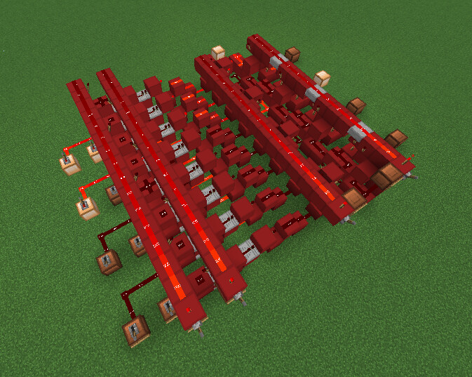
(the forum doesn’t allow me to attach more than one image)
What is the name of the warp for your build on ORE?: iuriineves2bitALU
Provide your results after completing the ORE Binary Quiz:
Binary Quiz completion certificate:
Completed by iuriineves in 6m44.894s on 4/7/2025, 20:36 UTC.
100.00% accuracy with 0/25 answers given incorrectly.
022aa7c1-11bf-4ef7-a092-f8fc1daec682-69757269696e65766573
472c5f4h5m131s29392r4k6k5h182a0t5f3t6d2wm97izdhim97j81wk
Do you agree with the rules?: Yes.