Hello everybody. In this post, I’ll explain what a PDCCA is.
So, what is a PDCCA?
PDCCA stands for Purely Digital Carry Cancel Adder. You might be familiar with regular CCAs and if you are, then you probably know they depend on signal strength to work. The PDCCA removes this dependency, making it a completely digital circuit.
How does a PDCCA work?
Let’s suppose we have two 4-bit numbers, A and B (though they can be any size)
Then the first step is to XOR all the bits of A with the corresponding bits of B.
So, for example for A = 0b0011 and B = 0b0100, you’ll do: (read from top)
0 XOR 0 = 0
0 XOR 1 = 1
1 XOR 0 = 1
1 XOR 0 = 1
So the result is: 0b0111 or 7.
The next step is to compute the carries. This is done using this equation C = !CC AND P OR G, where:
C stands for Carry
CC stands for Carry cancel
and G stands for Generation
The G signal is produced when both A and B are 1.
CC is the opposite, it is produced when both inputs are 0. But since the carry equation only uses its inverse, we can instead have CC to be 1 when at least one input is 1 and save an inverter.
The generation of these signals can be implemented with AND and OR towers.
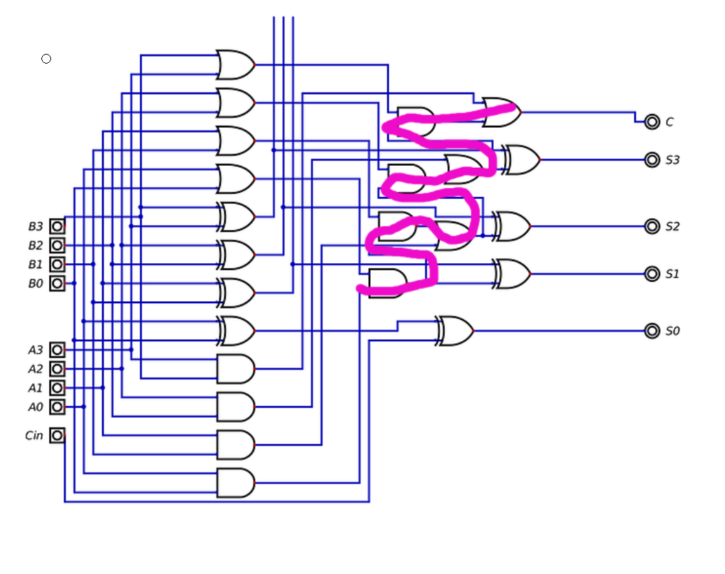
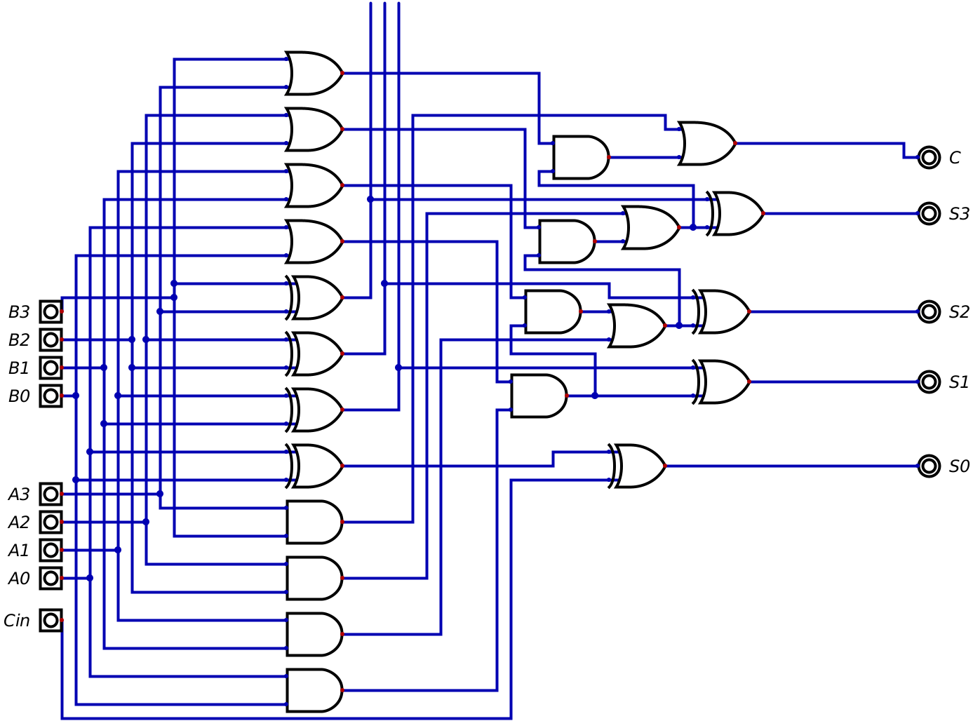
AND is for G and OR is for CC (we’re using the inverse of CC). Third tower is XOR. The output of the XOR is XORed again with the carry from the previous bit. For the first pair of bits, the XOR result is left as it is, or if we implement Cin (carry in), then it is XORed with the Cin input. The carry from the first bit is simply G. The output of the last carry circuit isn’t further processed in any way and becomes the Cout (carry out) output, which can be used to join multiple adders together to work as one. The output of the second XORs is the result.
Logic diagram
Screenshots
Uploading: 2024-06-30_15.41.46.png…
Uploading: 2024-06-30_15.41.57.png…
Uploading: 2024-06-30_15.42.05.png…
Uploading: 2024-06-30_15.42.11.png…
Uploading: 2024-06-30_19.03.21.png…