Minecraft name:
Sloimay
What’s a thing you have made which demonstrates sufficient engineering knowledge?:
I made a “terrain generator” using redstone.
I also made a 5hz Conics Graphing Calculator, and a 5hz Image-rotator, to name a few, but I won’t talk about those in this application.
What engineering work went into designing this device?:
I am going to talk about what engineering work went into designing the device, so I won’t explain in deep details which algorithms are used past just perlin noise and what’s needed for redstone.
The first intuition I had for such a project, would be to have a function f(x, y) which returns the height of the terrain at that XY column, and then print the terrain with a 3d printer using flying machines.
F(x, z) = height sounded familiar with noise functions, so I looked up how to compute perlin noise (a type of smooth random for people that don’t know) on YouTube and found plenty of documentation, it was exactly what I needed.
Here’s what I learnt:
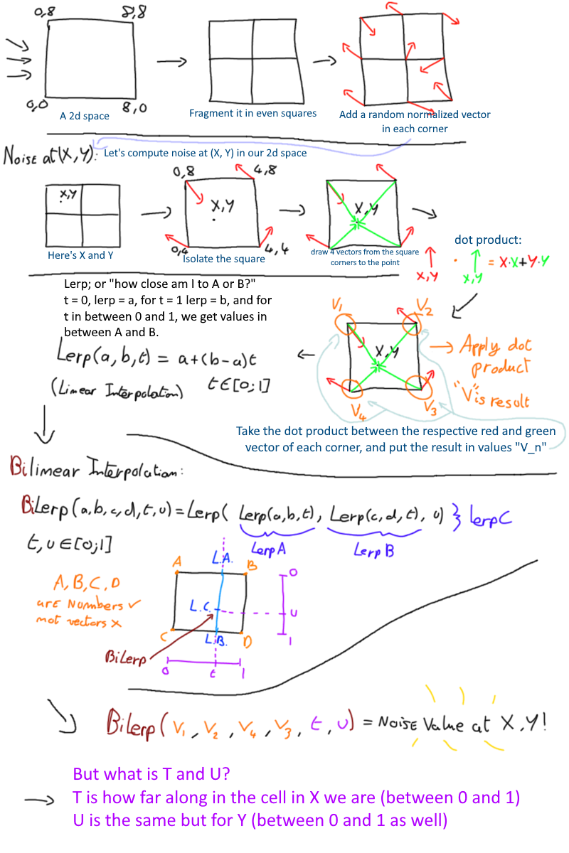
To setup perlin noise in 2d (2 coords in, a height out), here are the steps:
- Chunk your 2d plane in even squares
- Assign random normalized 2d vectors to each corner of those chunks
To pool perlin noise at a certain point in the space here what you need to do: - You get in which chunk the X,Y coordinates are in
- Draw 4 vectors (in green) from the corners to the point
- Take the dot product between each green vector and the red random corner vector associated with it to get a value per corner of the chunk.
- Now bi-cosine interpolate the 4 values in the corner with the coordinates within the chunk of X,Y, you have your final perlin noise value. (You can imagine bi-cosine interpolation as “take the 4 corners, and smooth their values out to create smooth heights throughout the whole chunk”)
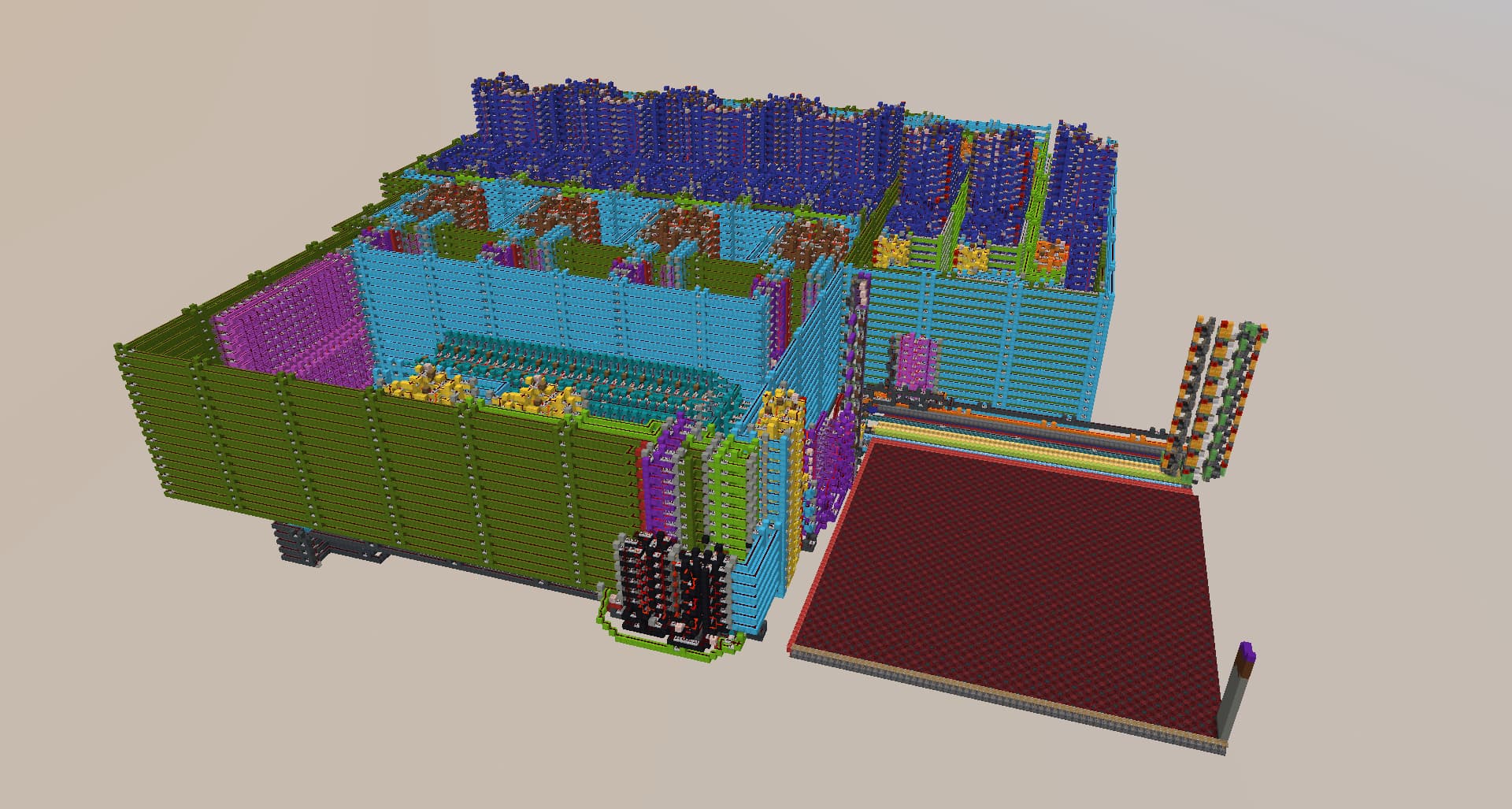
After learning about perlin noise, I quickly coded it up in python to see if it’d work and rendered a world using my python package: MCSchematic (mcschematic · PyPI) (shameless plug)
Now if this was a bit hard to follow, Figure 3 is almost what the algorithm is, just modified a bit so that it’s easier to do with redstone.
Good segway to: “what changed from software to redstone implementation”?:
- The bi-cosine interpolation at the end has been replaced with a less pretty but more efficient algorithm: bilinear interpolation (Bilinear interpolation - Wikipedia)
Bi-cosine interpolation requires 3 cosine interpolation calculations to be computer, whereas bi-linear interpolation needs 3 linear interpolations to be computer, which is way easier to do with redstone ( linear_interpolation(a, b, t) = a + t*(b-a) ); as linear interpolation (lerp) needs a multiplication and addition, whereas cosine interpolation needs a cosine unit, and multiple multiplications. - Another thing I changed so that it was easier to do with redstone, are the generation of the random corner vectors of each chunk. Instead of storing 2 16-bit values per corner, I opted for an easier solution (which is also how perlin noise is usually implemented) which would be to only have 16 possible normalized vectors per corner and store a 4bit number into each corner, and decode which number corresponds to which of the 16 vectors using a LUT.
I also coded that new version up in python to see how it would look like. This implementation didn’t look too different from the original algorithm. Prettiness was lost due to the switch from bi-cosine to bilinear interpolation but honestly, it’s redstone, so it looked good enough for me XD. I’m glad I took that decision.
It was time to make it with redstone, so I defined my constraints a bit. I opted for a 64x32x64 world area, so the world height would only be 5 bits. The calculations required fractional math as well so I needed precision after radix points, so I opted for the 16bit 8.8 fixed point format, for decent precision before and after the radix point, while it being expandable to 2^3 times bigger (5 bits to 8 bits after radix) calculations and printer area size.
I first started with making the adders and subtractors, then made a 16bit sequential multiplier using 2t looping CSAs (FEARLESS_'s one, what a weird magnificent thing). After that I was able to make a “vector dot product” circuit, and a “linear interpolation” circuit. Next was the “bilinear interpolation” machine which is basically 3 “lerp” machines put next to one another.
The computation components are finished, the last step was to make the “corner vector pool-er” which will make us able to pool the corner vectors of the chunk the coordinates we want the height of are in. It was done with a special type of 8bit RAM which can only be written to using shift registers and a data stream, and read randomly. That type of RAM was a good fit with my build, as we can split a byte into 2 nibbles, which is very convenient. The “data stream writing” was also better suited, as the corner vectors of the chunks are randomly generated (using hopper-dropper RNG), order doesn’t matter, so I do not need random-writing, only sequential writing.
Now all we now needed to do was to assemble the components together to create what Figure 3 is saying. And boom, perlin noise compooper :DDDDD (I made my components in a very user-friendly drag-and-drop way, which made control-wire hell very quick to go through.)
Now let’s talk about 3D Printing a little bit:
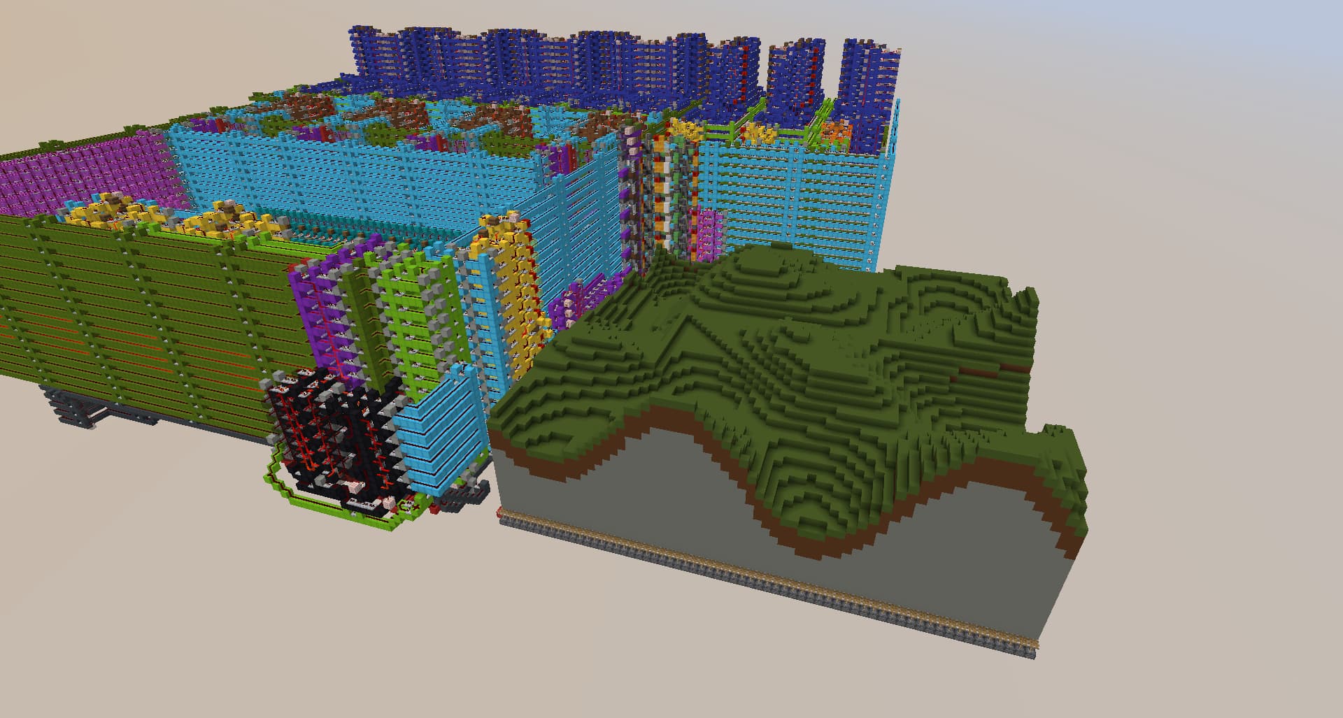
The printer is a 3D printer that prints XZ columns per XZ columns over an area of 64x64. Each column is 32 blocks tall. The printer will first build the column at 0,0, then 0,1, then 0,2 etc… until 0,62, 0,63 when it actually moves by 1 in the X direction and starts printing the second Z-row of the 2d plane, 1,0, 1,1, etc…
We input the height we want our column to be, the column-maker on the side builds the column (can be replaced with any blocks using more fancy redstone) then the flying machines pushes the column over to the desired X,Z location, using a first “Z” flying machine which pushes the column over to the correct Z-row of the world, and then an “X” flying machine which will push the column over to the correct X coordinate of the world.
If it was kinda hard to understand I could always show it working over on screen-share (or on Nano’s server that he let me build use).
The main problem of this part was working with flying machines and having to make 10k backups every minute in case something broke LOL, I definitely learnt how to deal with flying machine control logic and even though that was a pain, I’m glad I did it.
Little addendum:
The flying machines were made for the project by MythicalPingu, but the control logic was up to me as well as the column generation. I ain’t dipping my toes into slimestone LMFAO
I then connected the perlin noise compooper connected to the 3D printer by inputting the height it outputs to the column maker, which was our goal!
Some more final information:
- All perlin noise computations are done in fixed point 16bit 8.8 format
- It takes 5h on an overpowered server with /tick warp to render a world (so about 2 weeks in real time)
- The column generation uses concrete powder as “ink” that needs to be refilled manually (can’t generate those out of thin air) so instead of having a player having the refill them everytime a column is printer, I used a command block to set a new concrete powder block everytime one is used.
- It takes about uhhh, 2000 ticks to print a single column XD
Image/s and/or video/s of the device: