Index
An index of all Computational Redstone Guides by IAmLesbian, this one included.
Prerequisites
While there aren’t any lessons specifically recommended before this one, I would still advise an understanding of redstone mechanics. Namely the following components: Redstone, Repeaters, Comparators, Torches, Lamps, Levers, Buttons, Targets.
Logic Gates
Logic gates is an idealized model of a logic operation. When we talk about a logic gate, generally we aren’t referring purely to a specific configuration of blocks, but rather a relationship between the inputs and outputs of the gate. This relationship is what truly defines the gate.
IDENTITY Gate
An IDENTITY Gate is essentially no gate. If the input is on, then the output is also on. If the input is off, then the output is also off. Generally, this is not considered a gate but, technically, can be thought of the same as all the ones which follow.
NOT Gate
A NOT Gate is a simple inverter. If the input is on, then the output would be off, and vise versa. In redstone, generally this can be done with a torch.
OR Gate
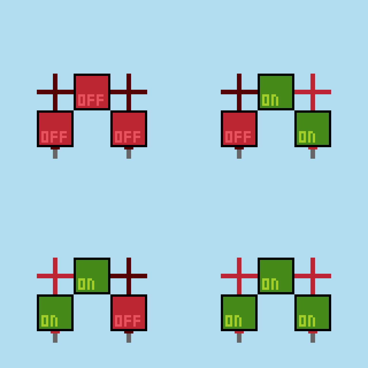
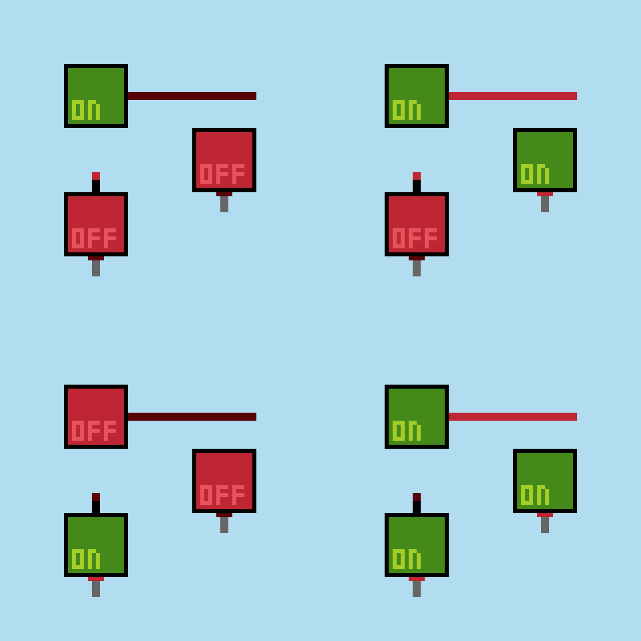
An OR Gate has 2 inputs, the output is on if either of the inputs is on. In redstone, this is typically done with both inputs powering the same redstone line.
NOR Gate
A NOR Gate can be thought of as an OR Gate with a NOT Gate on the output. The output is on only if both inputs are off. This is in direct contrast to the OR Gate’s functionality which serves as an example of what inverting the output can do.
AND Gate
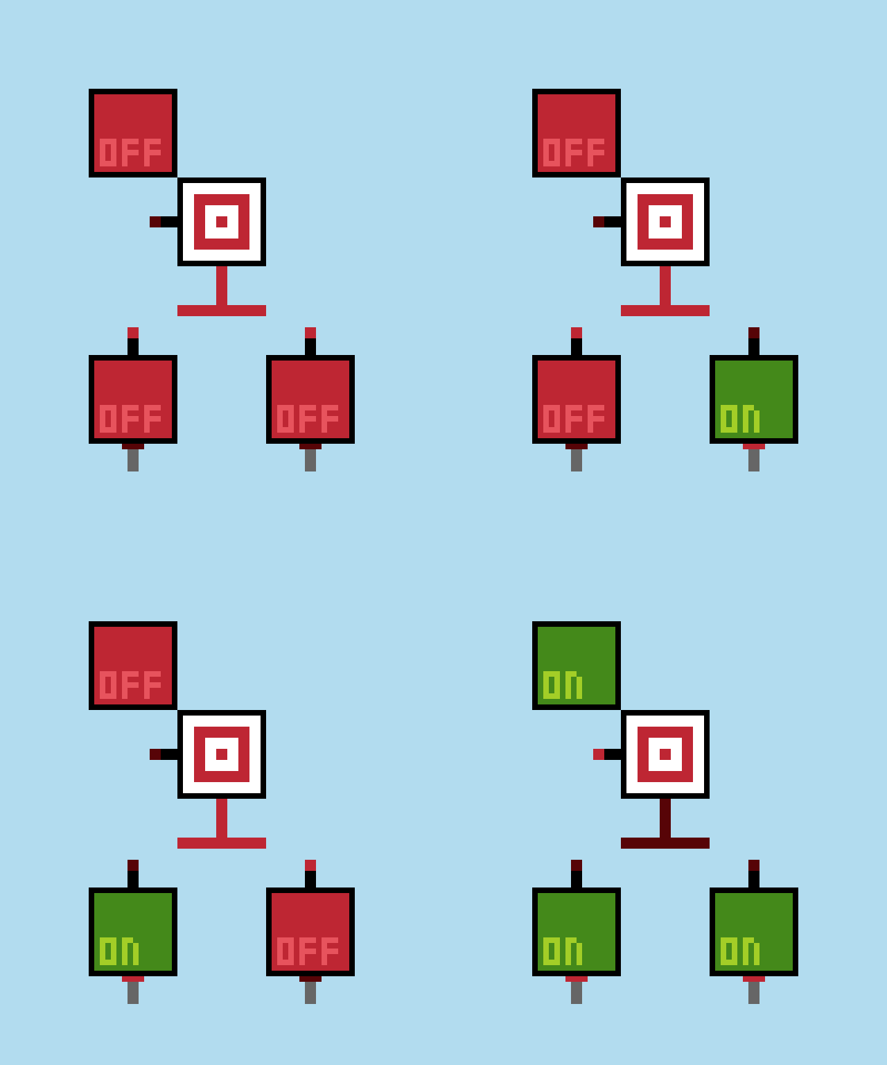
An AND Gate’s output is on only when both inputs are on. A common way to do this is by inverting both inputs, “OR-ing” those signals, and inverting that for the final output. The input torches keep the output torch disabled until both inputs are off.
NAND Gate
A NAND Gate, similar to a NOR Gate, is an inverted AND Gate. The output of a NAND Gate is on unless both inputs are on. Rather than inverting the output a second time, we can remove the inverter the AND Gate uses, because inverting twice is the same as not inverting at all.
XOR Gate
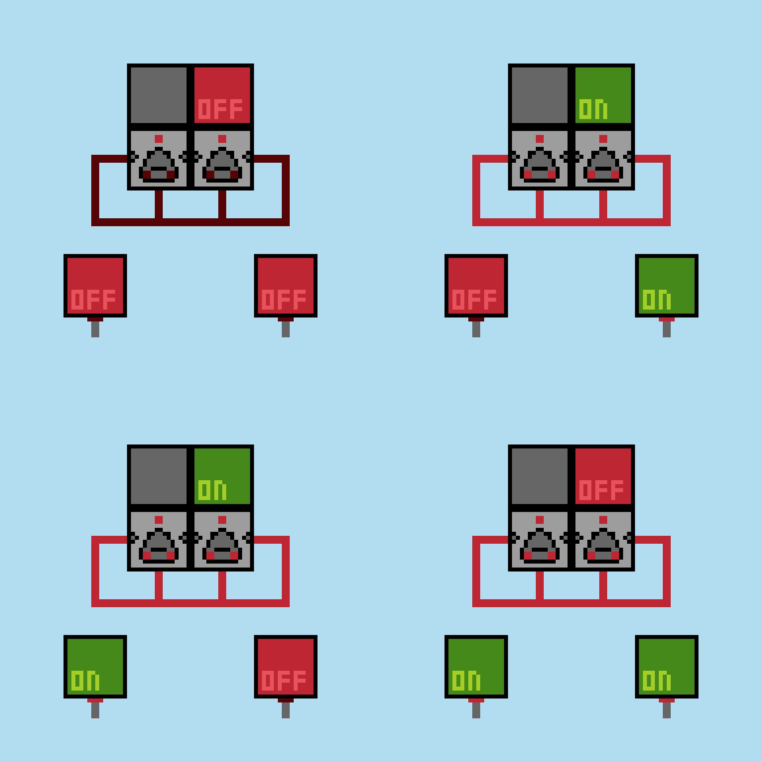
An XOR Gate’s output is on when the inputs are different. Another way to think of it is that the output changes whenever an input changes. Yet another way to think about it, is that the output is on when exactly one input is on. These different ways to think about the 2 input version of the gate can make it difficult to extend to more inputs in a way everyone will agree on. Here is a common design used in vertical redstone builds.
XNOR Gate
As with the NOR and NAND Gates, the XNOR Gate is also the inverted variation of the XOR Gate. This means the XNOR Gate’s output is on when the inputs are the same. A useful quirk of XOR and XNOR Gates is that inverting the output is the same as inverting one of the inputs. This can be seen more clearly in the design shown.
IMPLY Gate
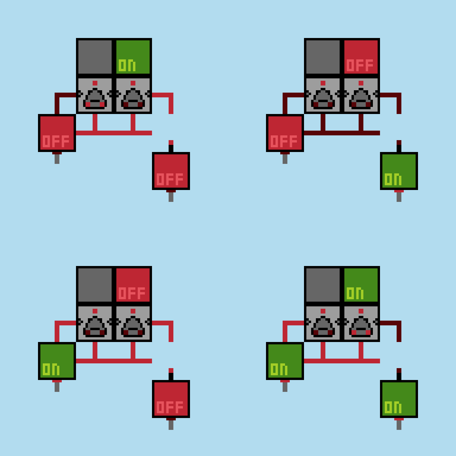
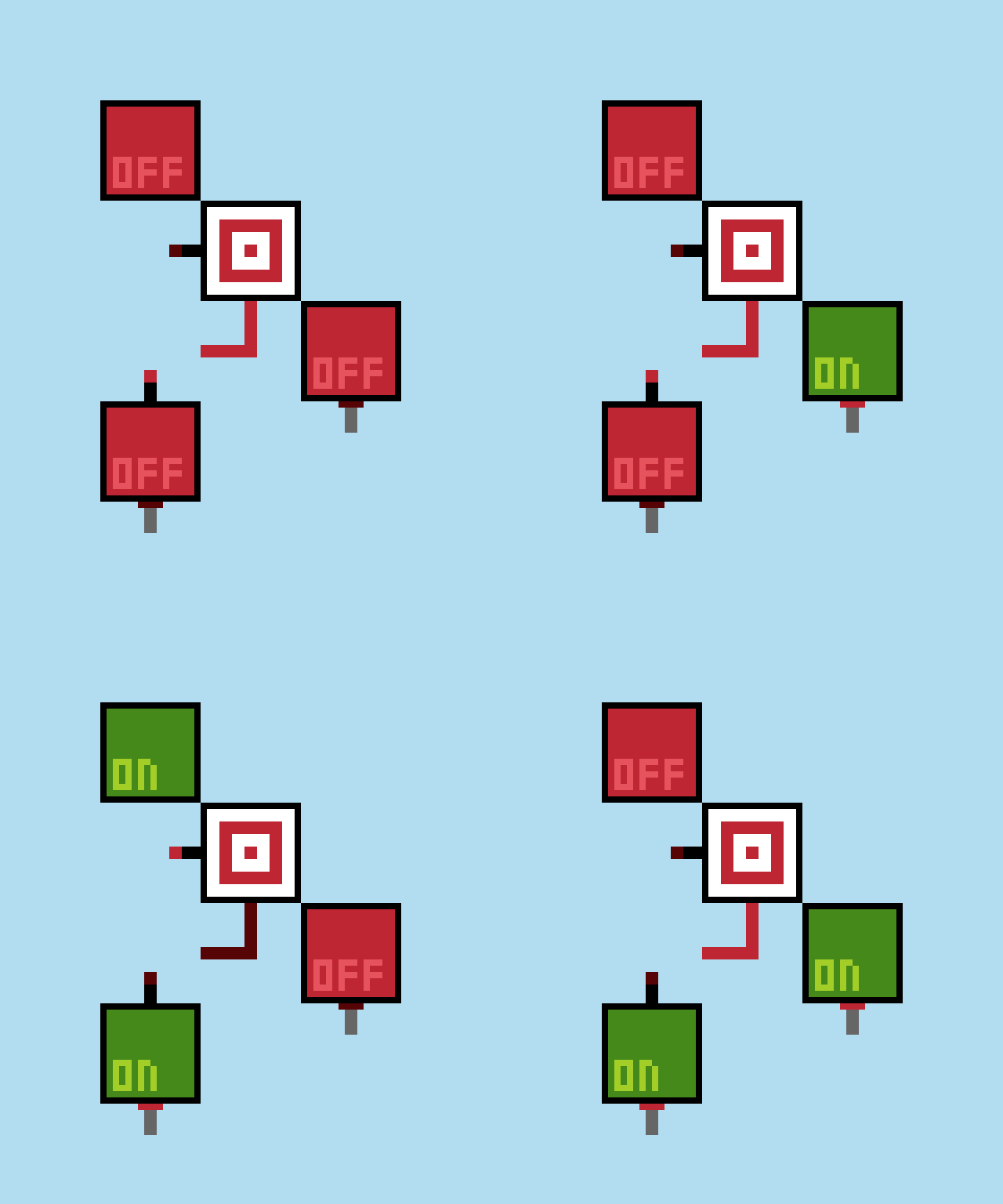
An IMPLY or IMPLIES Gate is one of the two less taught, and less known, gates. This is because it can generally be thought of as a variation on some of the previous gates. A IMPLY B means that when A is on and B is off, the output is off. Otherwise, the output is on. In the circuit shown, A is on the left and B is on the right.
NIMPLY Gate
The pattern holds true, this is the IMPLY Gate with an inverted output. For the case of A NIMPLY B, the output is only on when A is on and B is off. Once again, the circuit shown has A on the left and B on the right.
That covers all possible 1 and 2 input logic gates. Using these gates, you can create just about any circuit you can imagine. In another guide, I hope to cover that topic.
Continue
Boolean Algebra
An overview of Boolean Algebra, a system used to work with logic.

